


Description
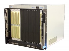
A component of the GENASYS platform, the GX7017 offers the flexibility to incorporate the GENASYS switching subsystem with 3U and 6U PXI instrumentation in one compact, PXI chassis. based on the 6U PXI architecture, the GX7017 can accommodate up to 9 GENASYS switch cards and 10 PXI modules, with 8 PXI slots supporting the GENASYS GX5960 digital subsystem. Up to 64 external resources can be connected to any of the test system’s switching resources / receiver I/O pins via a high performance, internal 16 wire matrix bus.
The GX7017 chassis incorporates the MAC Panel 6U SCOUT receiver. The SCOUT receiver offers a reliable and high performance method to connect the switch modules to a mass interconnect receiver, minimizing the need for cable assemblies. The SCOUT receiver is a “pull-through” design, with each switch card providing a “cable-less” connection to the receiver connectors - eliminating the need for cable harnesses and the associated reliability issues that come with cabled solutions. The result is a system interconnect design that is cost effective, reliable, and maintainable. The modular design of the SCOUT also allows for the use of a broad range of receiver connectors including high density, high current, and coaxial types. The 6U SCOUT receiver can accommodate up to 21 connector slots and over 8000 connections when fully populated.
Features
The GX7017 is a 20-slot 6U PXI chassis that can accommodate up to 19 switching or instrument cards as well as a remote PXI bus interface such as the MXI-4. In addition to supporting all of the PXI-1 resources, the GX7017’s PXI backplane provides an internal, high performance, 16 wire, analog bus via the backplane’s P5 connectors. Each of the GENASYS switching cards connects to this internal 16 wire bus, providing the ability to route signals from an external instrument to any of the receiver’s interface connections.
System power for the GX7017 includes an 800 W power supply for PXI modules and a supplemental 4.4 KW supply for the digital subsystem's VCC and VEE rails via the J5 connector located on the PXI backplane. The chassis utilizes a Smart power system which automatically adjusts the VCC and VEE voltages based on the programmed drive-high and drive-low levels of the digital instruments, minimizing power dissipation and overall cooling requirements.
To ensure adequate cooling, the GX7017’s cooling system includes 8, 100 cfm fans, with four located under the card cage and four located at the rear of the chassis, providing positive airflow per the PXI specification and high capacity cooling for PXI modules. This cooling configuration, in conjunction with air plenums within the chassis, provides airflow for all module slots and requires no additional rack space for inlet or outlet air. Additional cooling with dedicated fans is provided for the system power supplies which are located at the rear of the chassis.
The GX7017 chassis supports the monitoring of slot temperatures and system power supply voltages as well providing the ability to program or map each PXI trigger line from one PCI segment to another. In addition, the user can program the temperature monitoring function for specific warning and shutdown limits. All user specific setups can be stored in non-volatile memory as a user configuration and can be used as the default setup for normal chassis operation.


